A model rocket tends to roll as it goes up and in addition to this, some amount of thrust is lost in a transverse motion of the rocket.
A stabilization system is needed for this and, in some cases, wanted.
This project is based on the idea of autonomously actuating a secondary set of fins to have a desired effect on the rocket.
Side note: Below is a picture of the initial version of this.

1. An Overview
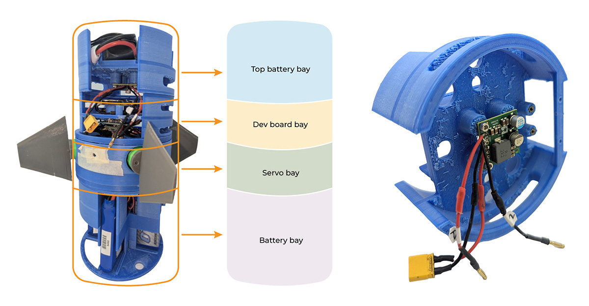
The design of this system was done with the goal of having everything modular. As you can notice that there are actually four parts of this system which are screwed together to make it whole. (see more)

I call the top part “Top Battery Bay”, the second part “Dev Board Bay”, the third one “Servo Bay” and the bottom part “Battery Bay”.
The idea behind this design language as explained is very straightforward. This modular design enables the user to add different capacity batteries, different servo motors, and different development boards. In addition to that in a case of damage to a part all you have to do it is to reprint it. In addition to that it is also easier to iterate on the designs. Let me get into more details of how these individual parts function.

The Top Battery Bay is the most boring part of the system as it only houses a small 1000 mAh 25 C LiPo battery to power the Teensy 4.1 microcontroller.
The bottom face of this part has a 5V down Pololu buck converter that feeds into the microcontroller.

The Dev board bay is very interesting. As shown in the pictures below, the top face of this piece has an RTC clock module (to keep the time even when the system is off) which is powered by a 3.3 V coin battery, IMU20948 a 9 degree of freedom IMU unit, and a BMPxxx altimeter from Adafruit. The altimeter is not needed for this particular project, but it is nice to have to gather altitude data. The bottom face houses a really capable Teensy 4.1 development board as shown. In addition to that I used a 128 GB high speed Samsung memory card.

The Servo bay is a penultimate piece in the assembly. There are four MKS DS95 high speed servo motors which actuate the four fins. It also houses two pull switches, one for the servos, and one for the IMU.


The Battery bay is the last part of the system. I can house up to 4 batteries. The setup I am running is 4 1000 mAh 35 C LiPo batteries in parallel giving a total capacity of 4000 mAh and nominal voltage 7.4 Volts.
Finally, for this section I would like to include some pictures.


2. Testing The Code (coming soon…)
In any closed loop control system you need to test the code and in this section I would like to show how I am doing it.