First off I want to start by crediting Lucas Stevenson (https://www.linkedin.com/in/lucas-stevenson7/) who had the initial idea, Kevin Howard (https://sites.google.com/view/kevinscadportfolio/home) for helping me with last-minute CAD and 3D printing, and my fellow SpaceLex team members for fruitful discussion.
In a typical rocket there are usually two recovery events; main parachute deployment, and drogue parachute deployment. Drogue is deployed at apogee to slow down the rocket enough so that it does not drift for miles, meaning you do not have to wander in the desert to recover your rocket. Main is used to really slow it down enough so that the energy during the touchdown is not enough to damage the rocket. The idea behind this project is about what happens during those two events. Specifically how to minimize the impact of the charges going off during these events. You might have something fragile that you want to easily endure during these two events and a system that absorbs the sudden acceleration experienced by the rocket when ejection charges go off during drogue and main parachutes deployment.
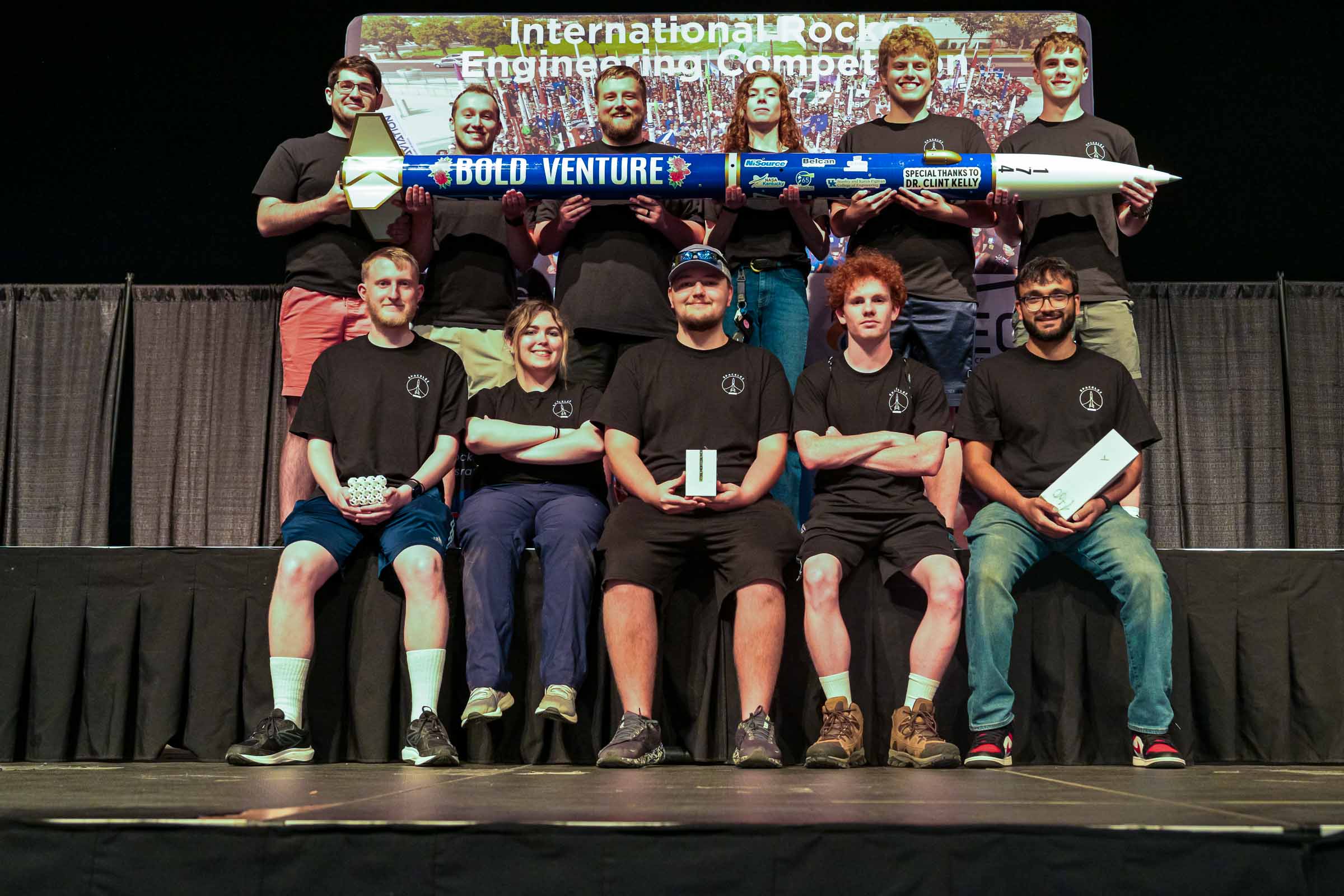
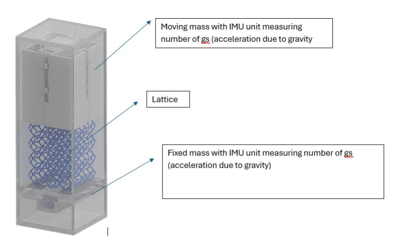
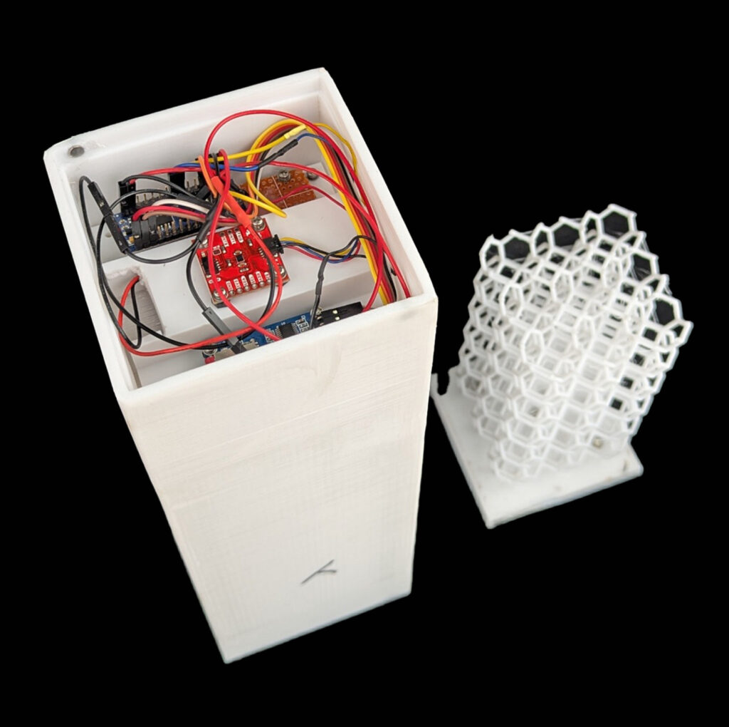
The 3U CubeSat (30 cm * 10 cm * 10 cm) in my hands in the picture above does that. It tests whether simple 3D printed lattices are a good way to be able to absorb shock during high g events. Inside of the 3U box there is a very clever setup to do this test. Like for any scientific test of a method you need a control case to compare your data with. In the illustration below the bottom space houses a fixed IMU, this measures the accelerations on the rocket, and on the top of the lattice sits another IMU measuring accelerations on the lattice that is sandwiched in between the two. Experiment is simple; just measure the two data sets for the two recovery events and find the efficiency by comparing the fixed IMU data against the movable IMU that sits on top of the lattice.
I think it is best if I start by going in detail about the lattice we chose to go with. The lattice material is PETG and it is 3D printed. The reason for this was mainly due to the temperature tolerance of the material, its glass transition temperature falls in the range ~80 to ~85 deg C, whereas PLA’s glass transition temperature is ~60 deg C. PLAs being close to the operating temperature near Midland, TX where the launch took place, it was decided to go against it. In addition to this the PETG and PLA being more common than others was the reason mainly these two were forerunners almost from the beginning. Also if ABS was to be used it needed to have an enclosure that takes care of the fumes while printing which was not available and therefor ABS was dropped out as a choice of the material (lol). Also, TPU was considered at one point but due to its springy nature it was not deemed to be suitable. I will expand on that now.
In addition to this the most valid reason for choosing PETG over others was how these materials deform and ultimately fail under load. Take TPU for example, if you print a TPU lattice you could see because of the elastic nature of the material it has linear or even higher degree stress-strain curve and it could expand to distances within the range of the lattice linear space we had for the payload. Also it deforms easily during that range and preserves its elastic property. In not so fancy language, it behaves likes a spring.
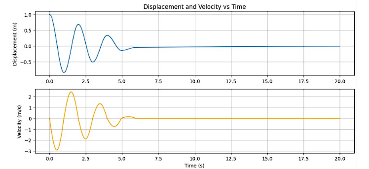
The above is a picture showing the case of a lightly damped system for example; mass spring system submerged in water. Water surrounding the moving mass does provide some resistance, essentially taking away energy from the system which results in decrease of oscillations and eventually reaching zero oscillations. This is what would happen if you have TPU for example. TPU essentially behaves like a damped oscillation system. It does not take a lot of imagination when it comes to the applications of this property but if you are trying to absorb the shock from ejection change going off this is not going to work. This will only induce oscillations and if the system is not underdamped whole rocket becomes a slinky pendulum. Also not to forget that the bigger issue is how a spring mass system in water weighs and that affects the rocket performance adversely. In addition to this a simple 3d printed lattice is easy to print and replace. Also you could have different operation range with different type of lattice. This means basically you need to print a new lattice and you are good to use that in a different lattice. Maybe this was the reason NASA is so interested in 3D printed nosecones. Hopefully now I have convinced all eight of you who will ever read that it is a good idea to pursue.
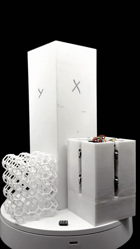
This picture shows the bend-dominating octet lattice along with the 3U CubeSat with the top mass with that sits on 3D printed lattice.
Slide the 3D printed lattice into the 3U box, put the top mass with IMU in it and you have assembled the system.
I will now go over the individual pieces.
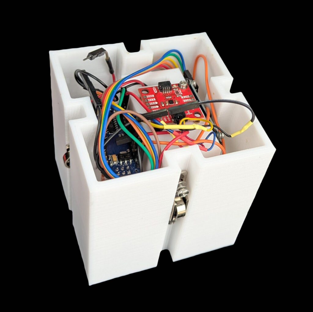
The Top Piece: The top piece comprises of Arduino Nano and SparkFun 6 DoF IMU sensor powered by 9V battery. The whole thing is made up of PETG with eight sliders in the four groves to have the mass slide inside of the 3U cube.
Lattice: The lattice is 3D printed using PETG filament. It is a bend-dominated octet unit cell PETG 3D printed lattice. It is specifically designed to not compress too much and shatter instantaneously. This makes it perfect for this application. This crushes the possibility of any oscillations but at the same time takes absorbs the shock from the ejection charges going off (technically since the payload was housed in the upper body tube such that it is inverted when the rocket is upright, the inertia of the top mass prohibits it to have any load imparted on the lattice when the charges go off, but when the shock cord is taut the mass imparts all the force on the lattice; each event is actually two sub events). I think this is the best place to tell the reader that we specifically designed the lattice to break at the main deployment and not at the drogue deployment. We wanted to play with the parameters of the unit cell and type of the lattice to show that one can print a lattice for a very specific rocket which experiences X gs in drogue and Y gs in main.
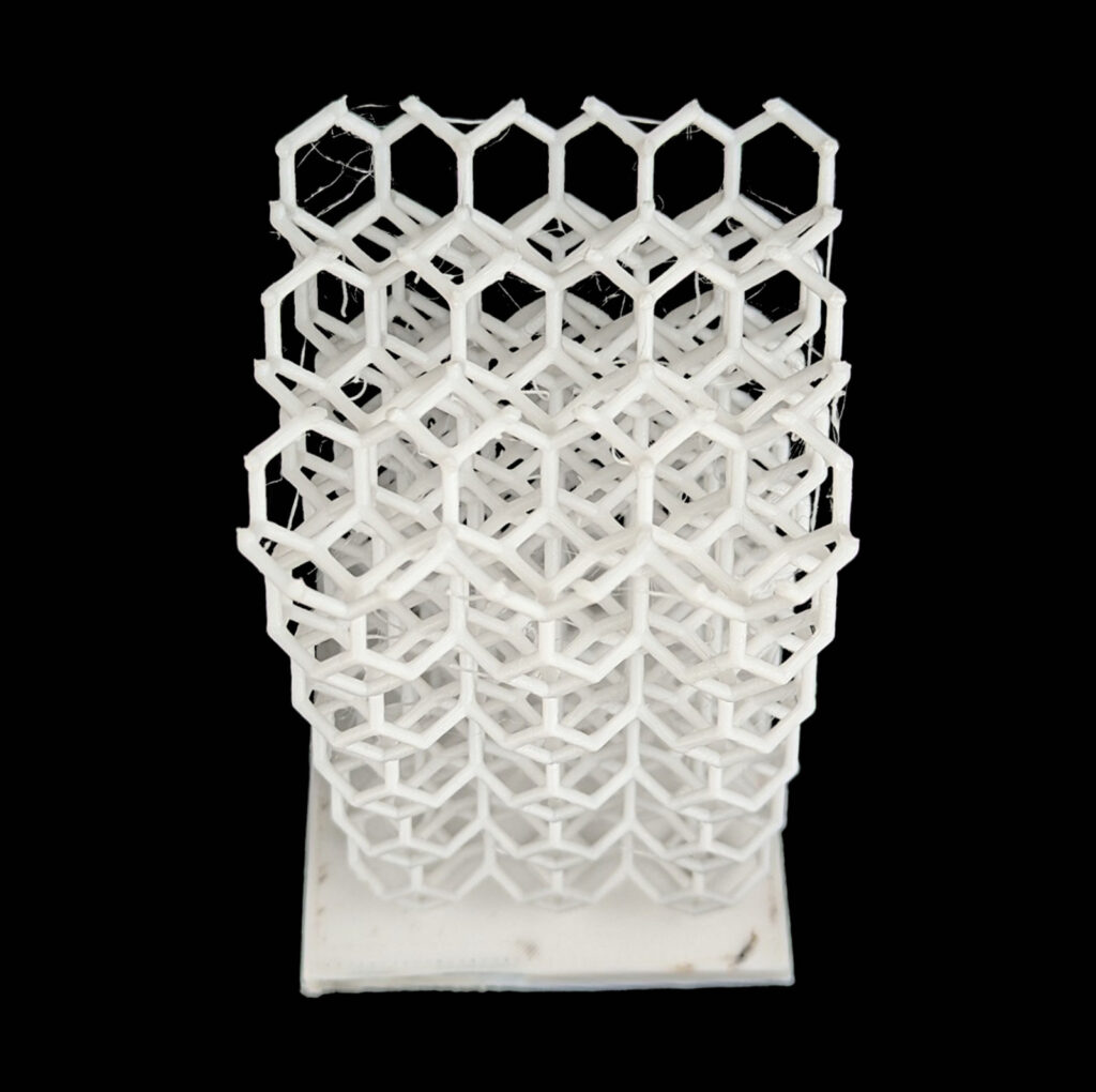
Bend-dominated Octet lattice; PETG
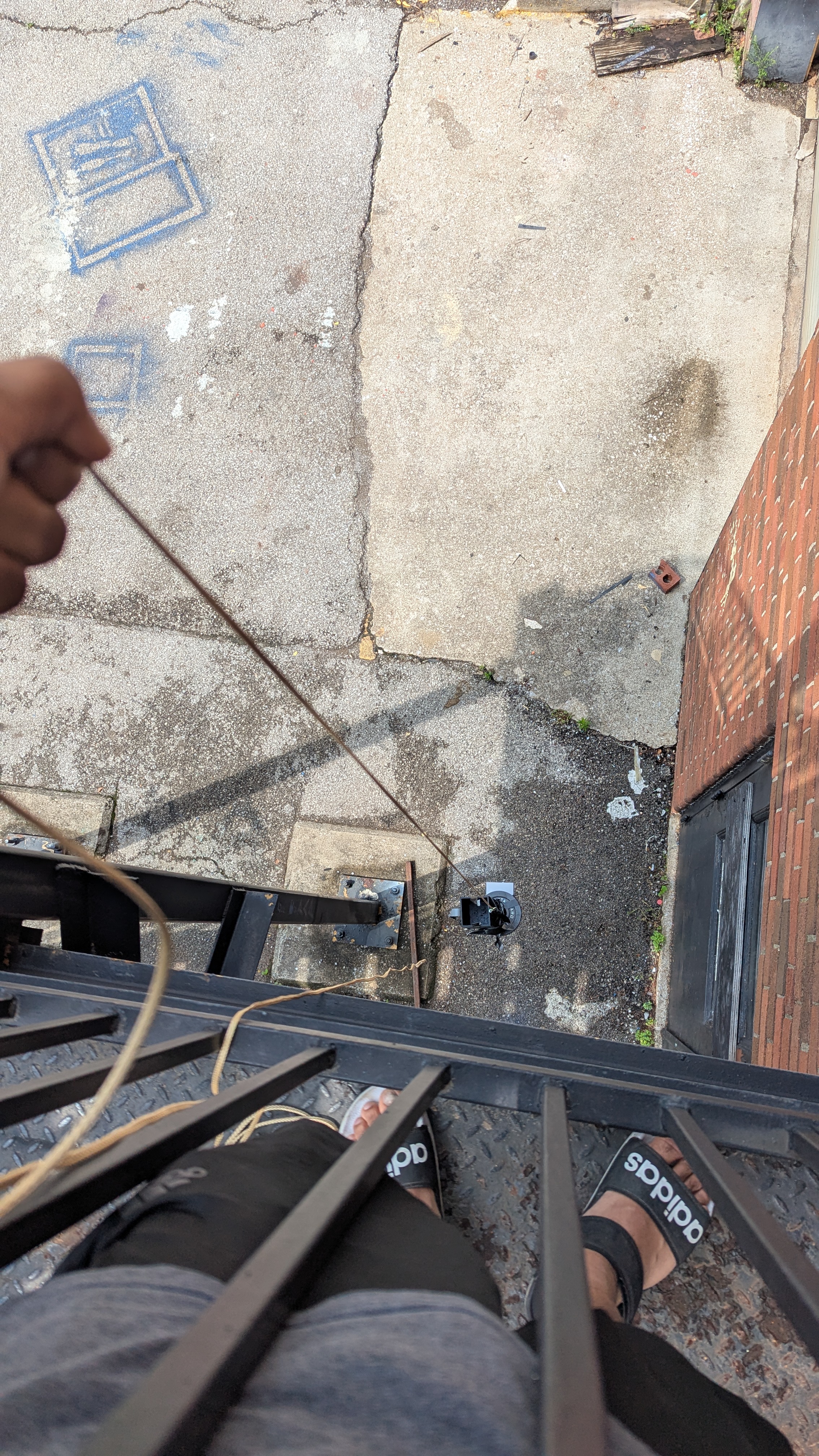
Since we had to make sure we are designing the lattice to break at main but not drogue we tested the lattice by dropping it with a phone from second floor. By varying the height of the drop different gs were imparted and it was made sure that the lattice breaks (absorbs energy) above the gs it would experience during drogue. We got that number from simulations.
Bottom IMU: This is exactly the same IMU and other electrons as the top piece. The only difference is that it is fixed to the box. This means it is fixed to the rocket hence measuring the number of gs the rocket experiences during these events.
Results: This is from the flight on June 2025 at IREC.
We designed the lattice so it would break when the main parachute opened but not when the drogue parachute deployed. This was our goal for the project. In the flight, the lattice didn’t completely break, but it was clearly damaged, which shows that it took in a lot of the impact. We had two accelerometers to measure how much shock was felt. One was on a moving mass that sat on top of the lattice, and the other was on a fixed mass without any protection.
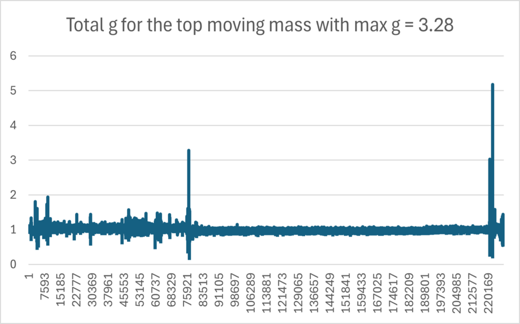
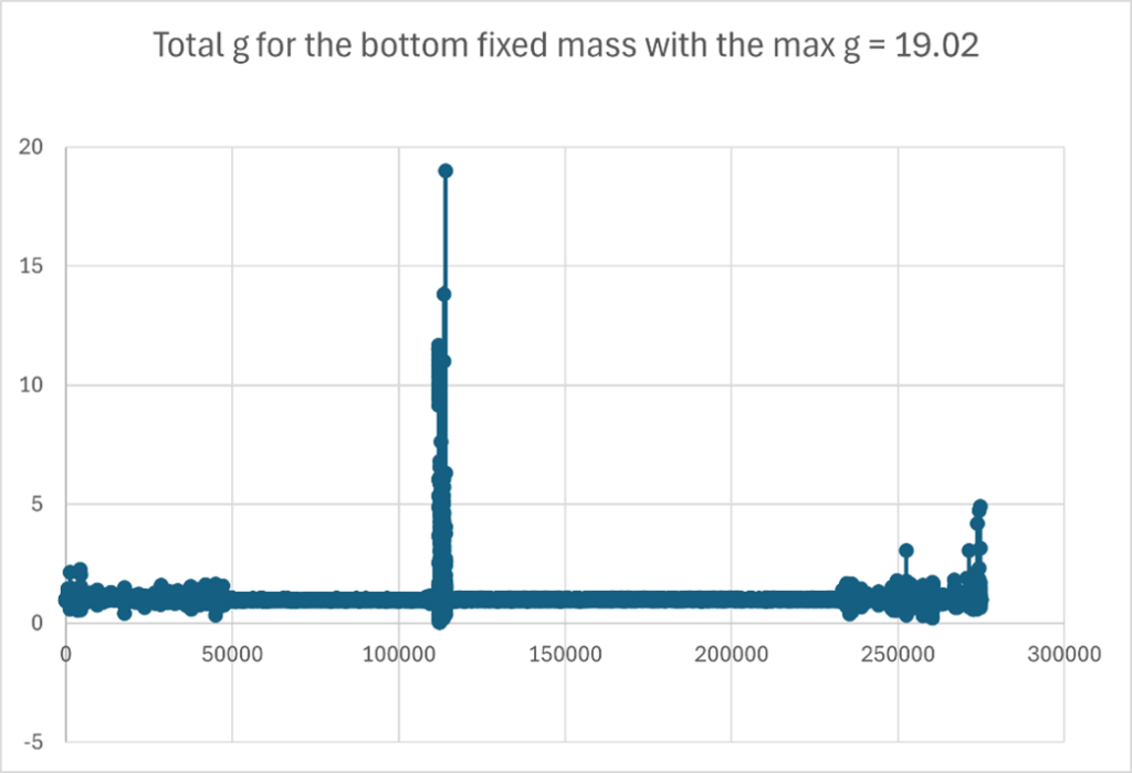
As you can see that the rocket measured 19 gs whereas the lattice experienced 3 gs. This shows a significant reduction in shock – exactly what we hoped for.
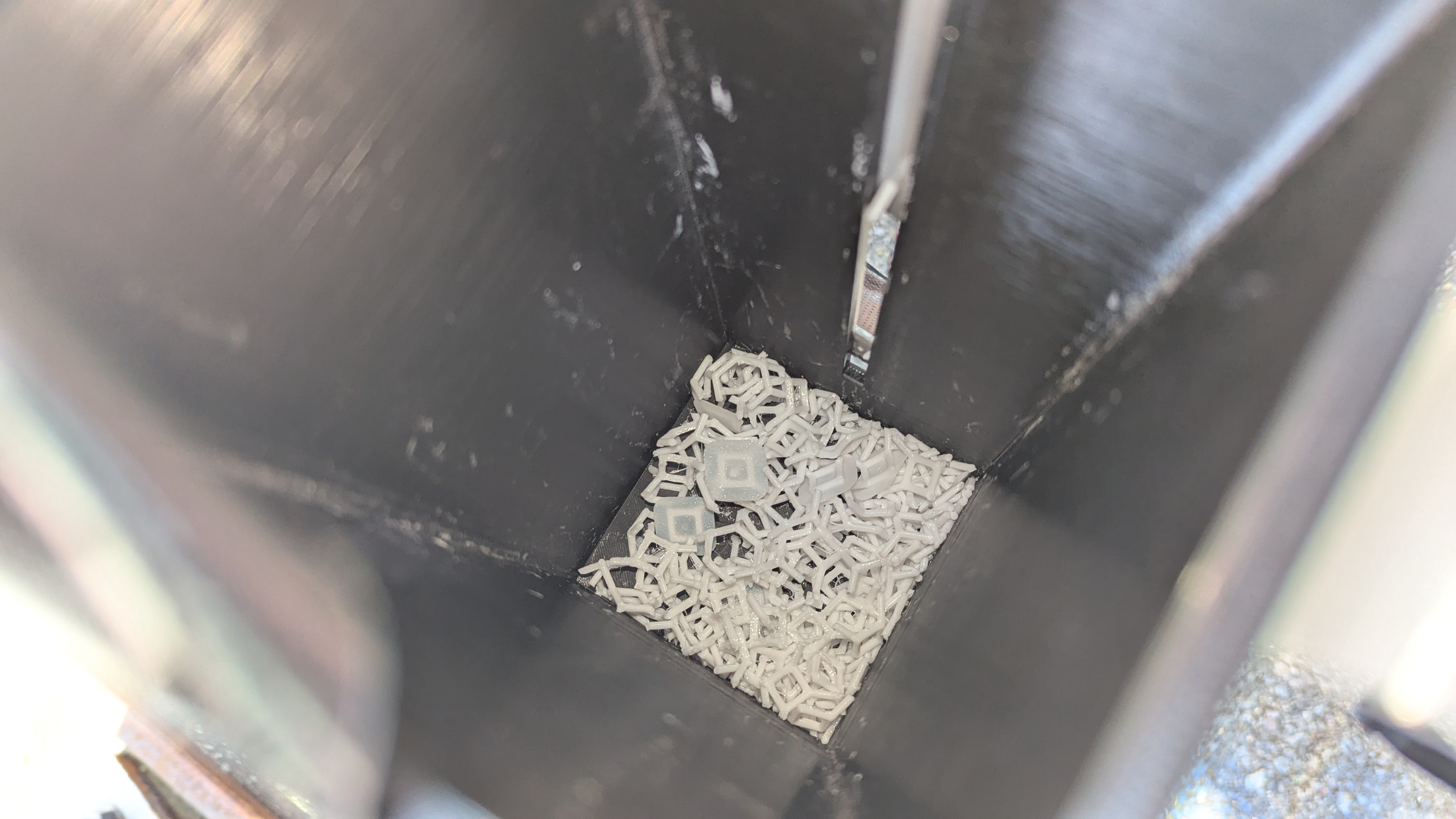
Now, below is the picture of the lattice that came out not in a powdered form. Not exactly what we hoped for but we believe that happened because the process of tightening of the shock chord is not exactly same as dropping weights. It is an incredibly difficult process to model and predict. What tends to happen most of the times is the total g is distributed among the there directions and the linear direction component might not be large enough to break the lattice. Therefore you might experience high gs but still end up with unscathed lattice (not enough energy absorbed). This is what we believe happened with ours.
Future Work and Improvements: A clear improvement could be to expand our design to test shock absorption in all directions. In this project, the lattice was only placed in the vertical (z) direction. In future payloads, we could plan to include lattices on the x and y axes as well. This would allow us to study how well the system can protect against sideways forces, which are common during chute deployment. Testing in all three axes would give a more complete picture of how the lattice behaves and could help us design a fully 3D shock absorption system for sensitive payload components.